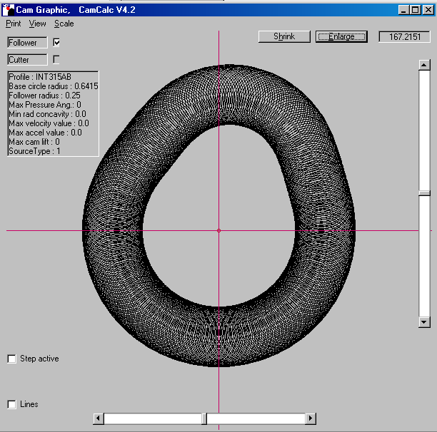
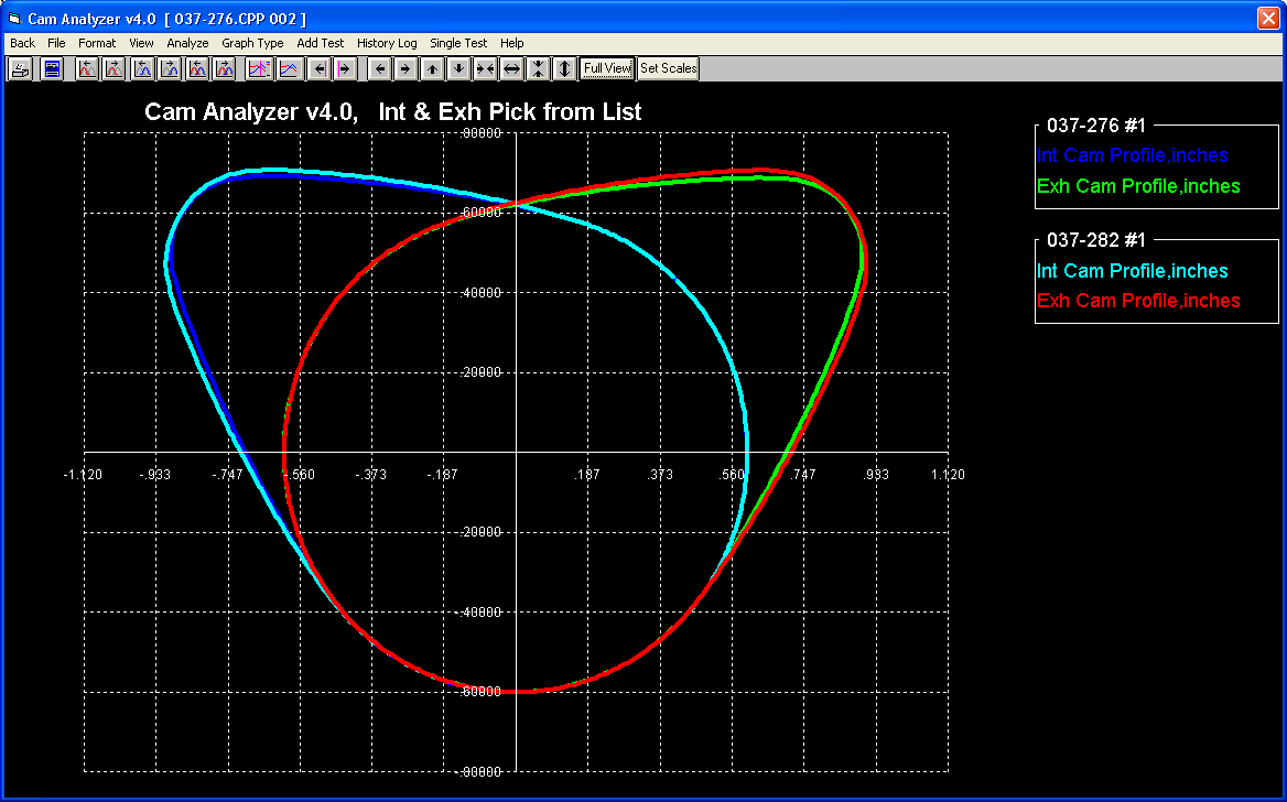
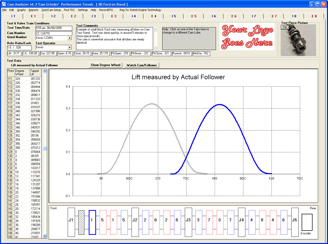
We can output profiles to suit CNC grinding on Landis and Toyoda CNC cam grinders as well as lift data for manual cam grinding machines using master plates. Cam Analyzer v43 for Windows XP Vista Win 7 Win 8 Win 10.
Andrews cam programs use an interactive intuitive graphical interface which makes it easy for beginning or experienced users to rapidly design quality cam lobes or analyze previously generated cam lift data for different characteristics and applications.
. This worked well at engine RPMs below 2000 which is 1000 cam RPM. Kip Fabre - Cam Motion. Not the same ole grind.
Cam lobes modeling process using CAD software like Creo involves an integrated approach which is tedious. The COMP Cams Lobe-Profile Library. The CNC control software translates the followers movements into dimensional data that can then be compared to the CNC design file.
Older roller tappet radius tappet and flat tappet camshaft engines from the teens up to the 30s set the valve lash close to 003-005. If there were no clearance ramps designed onto the cam lobe and the valve lash was set loose like 010 or above the. I havent been so impressed by camshaft as this one idle is very good idle torque is phenomenal but it will pull to 6k.
Without owning the original design profile data there can never be any quality control after grinding as there is nothing available to quantify the finished cam to. Cam profile designs are furnished with the lift and design data along with s96 and Landis p programming files. How to use MGIs Camshaft Calculator When shopping for camshafts from different manufacturers enter each of their supplied cam card specs into MGIs Camshaft Calculator.
Version only demo. By hoffman900 Tue Nov 16 2021 658 pm. Camshaft Design Program.
Fig2 Geometrical data for a pushrod cam follower mechanism. Computer Program to Measure Cam Profiles camshaft profiles by Hand or Analyze graph and report Several Various Computerized Cam File Formats like Cam Dr tm Cam Pro Plus tm csv p svl etc. Call today for your new billet cam Billet Turbo or custom work.
The rocker arm transfers the motion of the valve lifter riding on the cam lobe to the valve and increases the lobe lift by the amount of the rocker ratio which is typically 15 to 171. Adding the Lobe-Profile Library CD Dynomation6 and DynoSim6 users can model valve motion and engine output with unprecedented accuracy using the entire Comp Cam lineup. There are 12 months of free updates included.
Click to download the Demo version 2xx std. Motion Software and COMP Cams have joined forces to offer engine enthusiasts 3500 state-of-the-art lobe-profile files that you can instantly load and test. Ingram Engineering Cam Profile Designs is a custom cam profile design service for camshaft grinders engine builders and anyone needing a specific cam profile design.
Cam lobes are responsible for opening and closing of valves in an engine cylinder which are appeared on the camshaft. In this study the Modeling of cam lobes has been done to validate the idea of Design Automation. The XE cam profile is very aggressive and requires stiffer springs to control the low-lobe lift well.
A CNC process controls a mounted follower that moves from lobe to lobe then journal to journal where it is lowered against the camshafts surface as it is rotated 360 degrees. We measure cylinder head valvetrain geometry and use modern software to output camshaft lobe profiles to give the designed valve lift curves. I wonder if we could approach the issue of camshaft selection from a different approachcamshaft lobe design.
In fact the software allows to design valve lift law to calculate cam profile for the main type of valve train system to verify the valve train system with the spring load calculus and also to analyze the geometry of combustion chamber. Get a custom camshaft for Your engine. Click to download the Pdf instructions.
Mike Jones - Jones Cam Design. Carmakers are downsizing engines to boost fuel economy and to reduce CO 2 emissions. And the download link will be mailed to the email address you have used to order.
Ive got 330lb springs 165lb on the seat. Graphs of both the cam lobe profiles lift heights and the acceleration and deceleration rates are. Cam Lobe Design Software.
To view PDF file of user manual supplement of Version 43s new features with Adobe Acrobat. The cam is the XE270 218email protected and 512 lift. Professional Cam and Perfect Cam is the ideal and complete software for engineering team tuner etc.
Lobe lift sometimes called cam rise is the height of the eccentric portion of the cam lobe above the base circle. Camshaft lobe designers. CONCLUSION OF CAST CAMSHAFTS.
Meaning the valve lift is a constant ratio compared to the cam profile lift. An interactive camshaft calculator where engine builders can see how valve overlap and boost efficiency is affected by a camshafts physical design. Cam designs made with Andrews cam programs work period.
Danny Crower - DCR. They have to meet much tougher corporate average fuel economy requirements in. This is a real problem for the grinder when checking the Jerk or 3rd derivative of the production cam as Jerk can get very large in all the wrong.
When purchasing a camshaft enquire which material the camshafts are produced from. The majority of my cam profile designs are for conventional valve trains. Ones that I know.
Another trend impacting camshaft design is the move to smaller turbocharged engines. Yes we even dyno test our camshafts Turbos. This material is exceedingly scuff-resistant and is the only material for producing quantity OHC performance camshafts.
An example would be if the rocker arm ratio were 15 to 1 the valve lift would be the cam lobe lift multiplied by 15 at any point. Fig3 The cam and bucket tappet for valve lift Design A. Programs will run on any PC with a Win XP Win 7.
Billy Godbold - Comp Cams. Andrews Products is a full-service manufacturer for camshaft design software and related technical training to support your complete development process from basic designs to finished parts. Our camshaft design programs allow end users to examine multiple designs in a short period of time minutes.
For maximum power Lugging torque. Cam lobe material to form a matrix of carbide this material will cut glass on the cam lobe. A full cam profile can be automatically generated for you based on the opening and closing points or lobe center angles and duration and lift heights that you specify or you can enter your own measured or existing data.
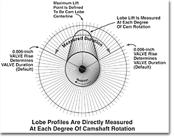
The latest in digital camshaft design testing equipment. The camshaft is defined by valve lift and duration which is further defined as opening and closing points. The cam lobe design.
Context if the cam and cam tappet surfaces each have surface finishes of 025 micron and the lubrication film at its. With the buyouts people passing people retiring curious as to who is left designing camshaft lobes. As we all know the purpose of a camshaft is to open and close a valve at a certain time.
Fig4 Bucket tappet cams for valve lift Designs A-E. Fig1 The cam cam tappet valve and valve springs. Each cam profile design is exclusive to the original customer and.
We offer two basic packages for lobe designs. These cams typically have more exhaust duration to push more rumble into the exhaust system.

Camcalc Software For Cam Lobe Analysis Cnc Programming
Cam Design Cat Cams Performance Camshafts

Camshaft Technology Andrews Products
Cam Design Cat Cams Performance Camshafts


0 comments
Post a Comment